| Back to |
IMPROVED CLEANING OF HIGH VOLTAGE INSULATOR IN ESP
Delivered at the 6th International Conference on Electrostatic Precipitation (VI ICESP)
M. Koralun, Instytut Energetyki, Gdansk, Poland
| Back to |
IMPROVED CLEANING OF HIGH VOLTAGE INSULATOR IN ESP
Delivered at the 6th International Conference on Electrostatic Precipitation (VI ICESP)
M. Koralun, Instytut Energetyki, Gdansk, Poland
W. Wawrowicz, DOLNA ODRA Power Plant, Poland
Abstract
The paper presents a new concept of continuous air-washing of inner surface of the support-brushing insulators in ESP.
The laboratory model investigation stand and anemometric sampling are described. For comparison of modelling results an integrate "effectiveness index" has been used. The paper includes a brief analyses of economical aspects of modernization of insulators cleaning system.
Investigations have been partially sponsored by DOLNA ODRA Power Plant.
Introduction
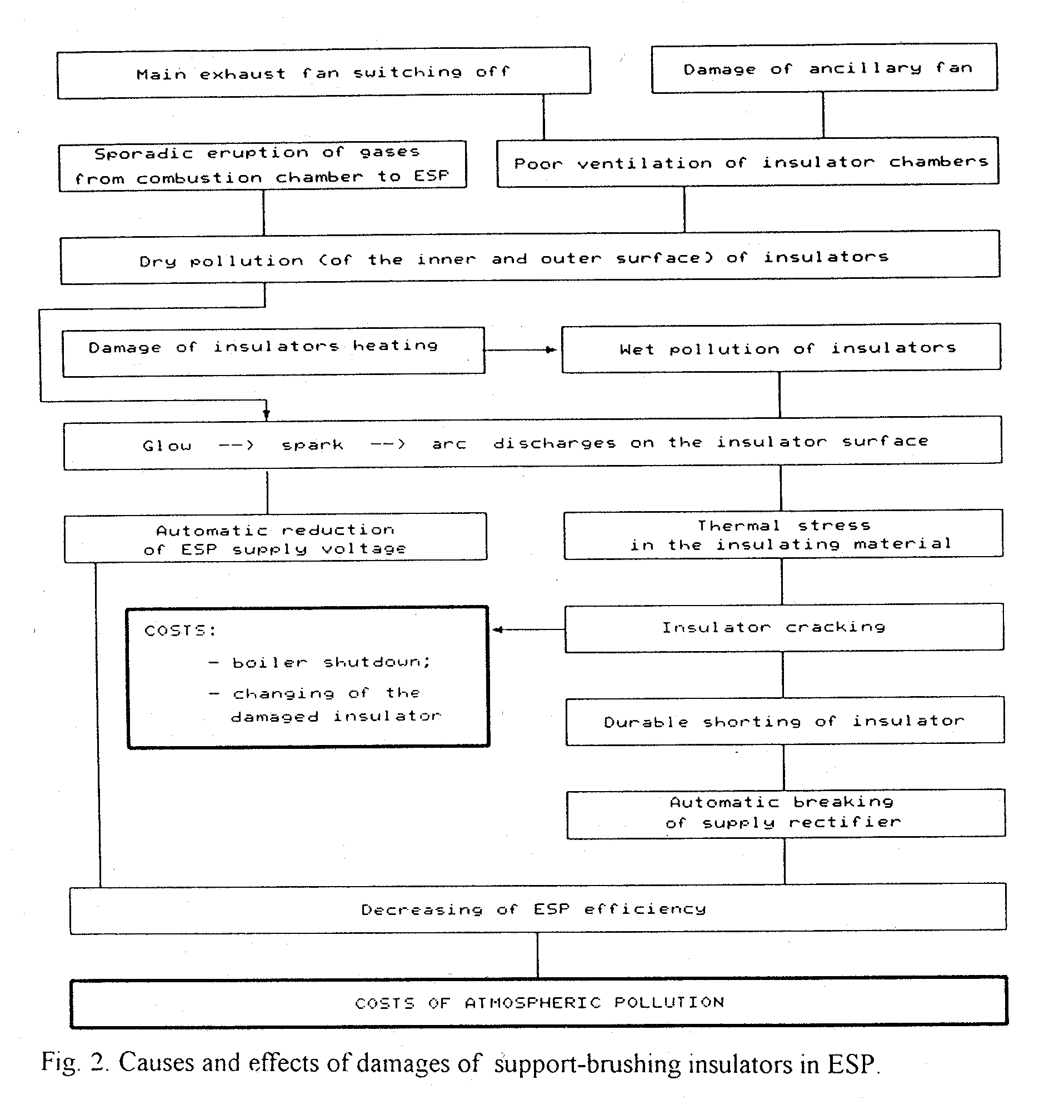
A high voltage insulator - working, in extremely difficult conditions - is one of the weakest elements in ESP reliability. Fig. 1. shows an example of damaged insulator, Fig. 2 - causes and effects of damages.
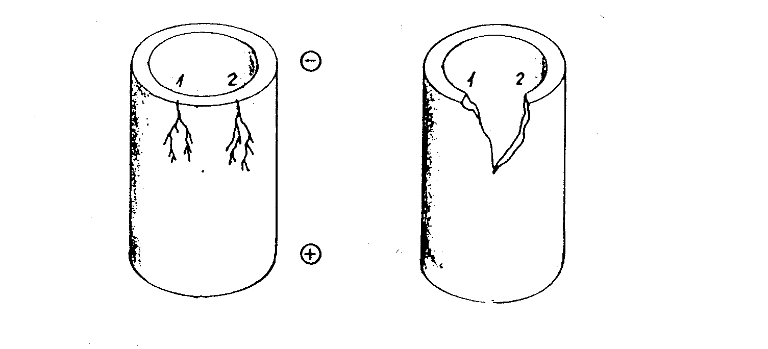
Fig. 1. Mechanism of thermal destruction of a support-brushing
Insulators: Surface discharge paths and cracking
of insulator body.
Polish Standard PN-87/M-31429 recommends a continuous washing of insulators by pre-heated
air or dedusted gas, but does not precise the manner of the flow of the washing medium.
In most solutions the cap of an insulator has two holes through which the atmospheric air is is sucked into insulator and flows there near vertically with a velocity of about I cm/s. Such velocity is not enough high to prevent the dust sedimentation on the porcelain surface. For example: to the sizing dust - gas channels v = 15 m/s is usually assumed.
The next disadvantage of present solutions is as follows: At the instable action of boiler burners, it occurs, that the static gas pressure in ESP - being normally negative - reaches transiently positive values. In this case the short return-flow of gas through insulators takes place.
As a result, some quantity of dust is emitted to the insulator chamber, causing the impurity both inner and outer surfaces of insulators.
New Concept of Washing
To avoid the disadvantages described above, a new concept of washing device was elaborated (Fig. 3.).
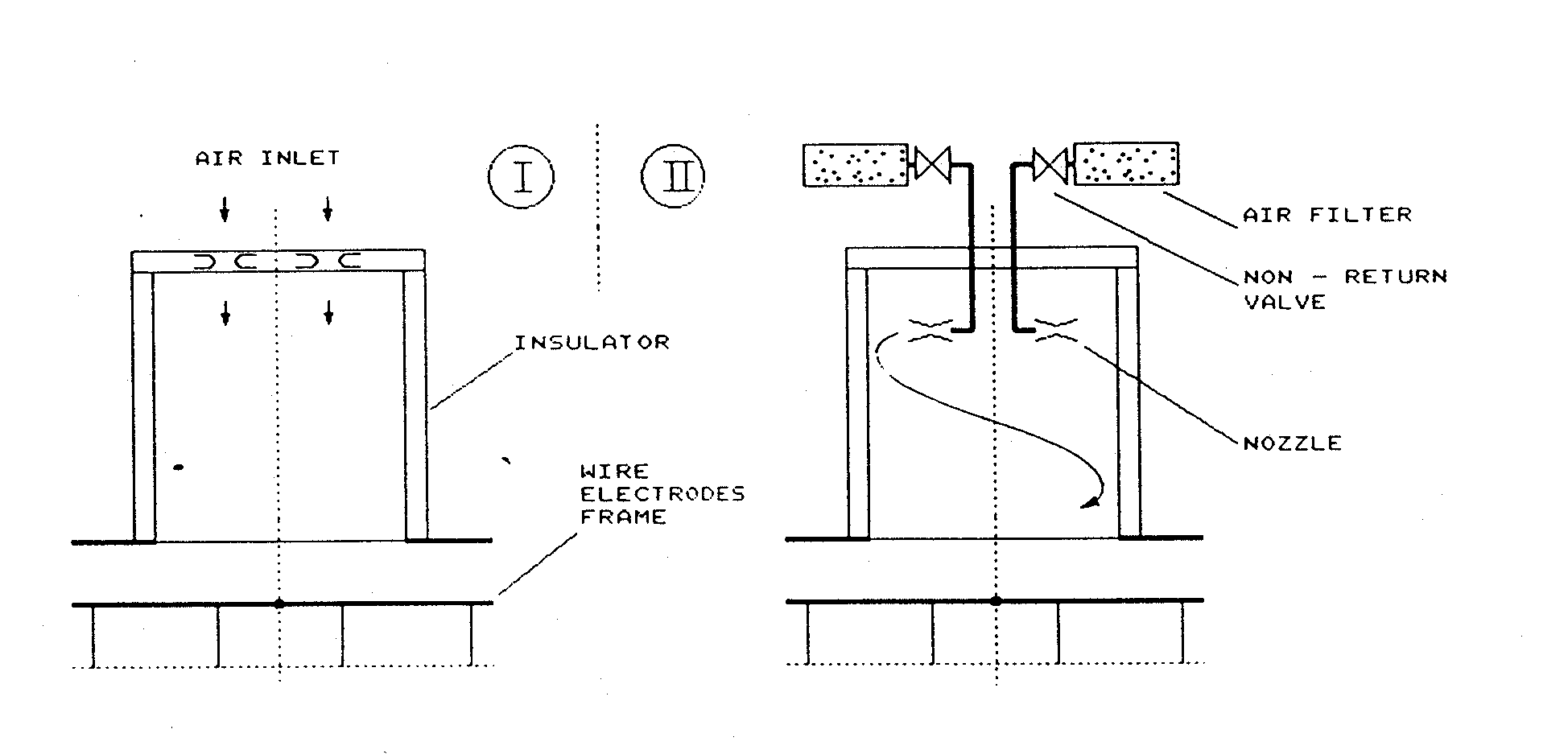
Fig. 3. Air flow inside insulator: Before (I) and after (II) improvement.
Air, after being heated in the insulator chamber is dedusted in a ceramic filter, and then flows through non-return valve and accelerating nozzle into insulator, being sucked by the negative pressure in ESP. Every insulator maybe equipped with one or two nozzles.
Flowing out from nozzles, air is moving along a helicoidal trajectory near the inner surface of insulator with enlarged velocity, removing sedimented dust and also preventing its sedimentation.
The flow acceleration in the nozzle depends on its shape and on the pressure difference available.
Having, only a small space inside the insulator we must apply a short nozzle. Good effects were obtained at de Laval type one, with a hole 10 mm dia. approximately.
Model Investigations
The cleaning arrangement was investigated in one-to-one scale in laboratory conditions, with air at temperature about of 20 C, but without dust. The model stand is schematically shown on fig. 2.
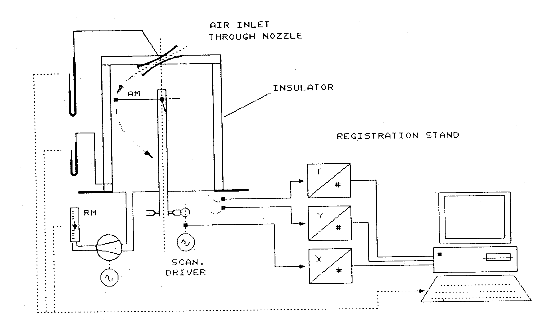
Fi- 4. Insulator washing model investigation stand.
AM - anemometer, RM - rotameter
Air was flowed into insulator by one or two nozzles, and sucked from the lower part of insulator by two vacuum - cleaners in parallel ensuring a negative pressure inside insulator up to 1,6 kPa.
Air velocity was scanned by a hot-wire anemometer, with near symmetric directional sensibility. The sampler was mounted on the end of a slender support linked with a rotable column, placed centrally in tile insulator.
The sampler has two degrees of freedom: vertical and rotative. It was moved continuously in horizontal direction, and after every full tour it was released and jumped down for 10 mm, tourning and jumping being repeated.
Thus, the velocity of air was scanned near the porcelain, at the distance not greater, than mm from its surface. Eventually, we obtained a velocity map (Fig. 5.) of a length:


where:
v - local velocity of the air"
A - area enclosed by tile scanning
(Note, that I, having, it is true, the physical dimension [m.3/s], is not a flow, since the vector v is not ortogonal, but near - parallel to the surface of insulator!)
For a chosen nozzle, mounted horizontally inside the insulator, it was obtained:
IH = 0,619 m.3/s
For the reference, by a random vertical flow through insulator it was calculated:
IV = 0,012 m3/s
A non -dimensional quotient x may be applied as a quality ratio of washing-. In our example this will be:
x = (IH (IV) (0,619) : (0,012) = 51,5
(2)
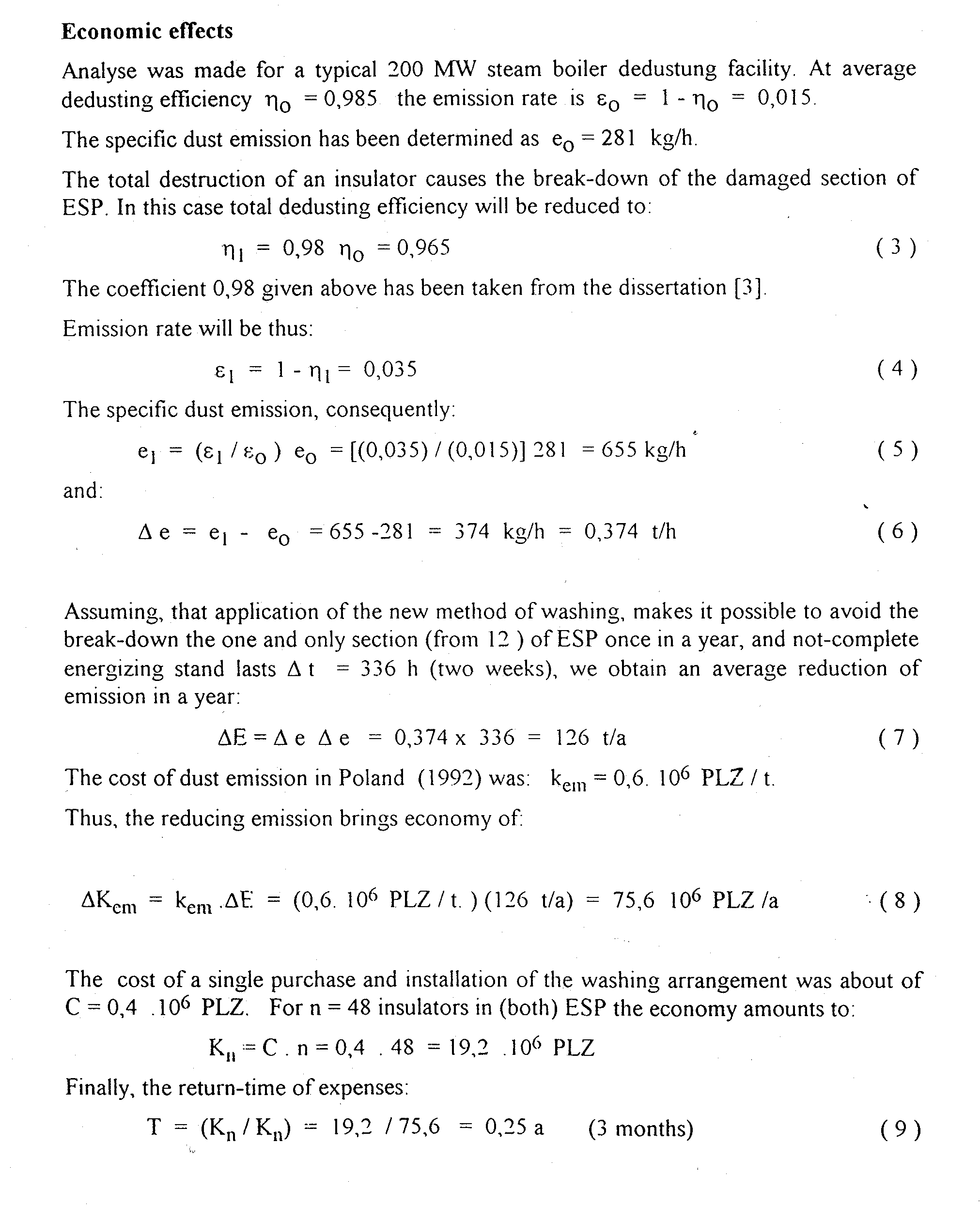
pieces) in both ESP of a 200 MW steam boiler in DOLNA ODRA Power Plant in 1993). The washing appears so effective, that no insulator destruction occurs.
References
1. Koralun M., Wawrowicz W., Wilczewski T. Arrangement for cleaning of
high voltage
insulator's in ESP. Patent No 296 596. Polish Patent Office,
1996.
2. Koralun M. Self-cleaning- of support-brushin(-, insulators in ESP.
III. Conference ESP,Cracow, Edit. by UNIVERSITAS, Cracow, 1992.
3. Knitter J. Analyses of energo-economic factors influencing- to ESP supply control in
power plants. Dissert.,
Electrical Department of the Technical University of Gdansk, 1984.
Back to the This Old Box
page.
Last updated: May 10, 2009.
Copyright © 1997 TRK Engineering
Services, Inc. All rights reserved.
For more information contact: TRK Engineering Services - 95 Clarks Farm Road - Carlisle,
MA 01741 - Telephone: 978-287-0550 - Fax: 978-287-0569 - email: trkeng@apcnetwork.com