| Back to |
Werner J. Frank
WALTHER & CIE AG, Waltherstr. 5 1, D-51069 Cologne
Preliminary studies of the existing electrostatic precipitator (ESP)
The reasons for upgrading an ESP are nowadays usually far more diverse
than simply a replacement of parts involving no new performance guarantee but only a
materials guarantee on the components replaced or added.
Upgrading mostly means taking account of stricter inlet and outlet requirements resulting
from the latest emission limits set by public authorities. For this reason a comparison of
the original and new rating specifications is imperative. In doing this it is
important to look at as many as possible previously taken measurement readings, especially
the measurements made in the course of acceptance tests, and to compare and evaluate them
with reference to the required future performance.
New inlet conditions may result from modified or increased output of the plant.
One of the important preliminary studies to be carried out on the existing ESP is the
determination of the flow distribution inside the ESP. Deleterious boundary and hopper
flow should be included in such measurements.
Another important preliminary study relates to the electrical characteristics of the
individual fields in the system under normal load. This assessment can provide the basis
for derivation of an optimized electrode geometry.
Results obtained from the above-mentioned studies will, of course, only be useful if the
existing system is in a good state of maintenance and repair.
Optimization of ESP inlet conditions
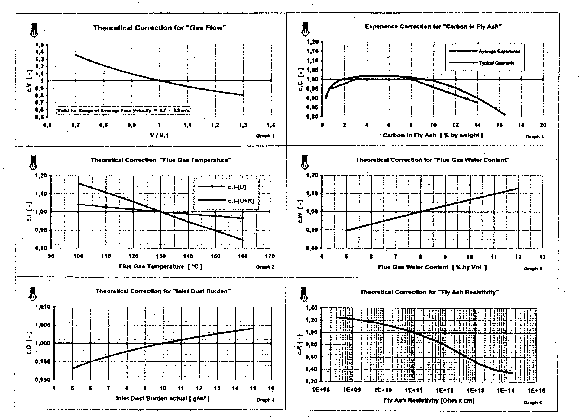
Looking at the essential parameters affecting the sizing of ESP'S, it becomes clear that checking and, if necessary, optimizing inlet conditions by means of measures taken in the plant to be dedusted will often be more effective than modifications to the ESP Itself Most operators of ESP's are aware of the very pronounced effect of, for example, boiler load on the stack opacity. Similarly, they are also aware of the unfavorable effects of poor process air control. Regarding the gas flow, overall dust precipitation performance follows the Deutsch migration velocity (wD), influenced to a greater or lesser extent by grain size distribution in the raw gas. Together with the other major inlet parameters this effect is presented in graphs I - 6 (Fig. 1) as a direct influence on changes of the ESP penetration, given as

Accordingly, it swiftly becomes evident that the improvement of an ESP should necessarily be accompanied by carrying out checks on and, where applicable, improvements to the production plant because optimizing

Fig. 1
this will in almost all respects result in an appreciable improvement of the performance of the ESP.It goes without saying that difficulties may also arise from modification of the production plant: in particular, changes of fuel, increased load, DeNOX retrofits and, not least, typical signs of aging in the plant itself However, the often considerable potential for optimizing inlet conditions for the ESP should be fully exploited so that the most effective use can then be made of the usually limited space for ESP modifications.
Retrofitting flue gas conditioning (FGC) systems
The effect of FGC can reduce the otherwise necessary SCA of an ESP
considerably. The reason for this lies in the dramatic improvement of the major inlet
parameters for the ESP. Normally, there will be a change in electrical field behavior.
Most time power consumption will rise considerably, using more efficient the capacity of
the high voltage supply.
Looking at the various FGC systems in general, the major requirements are commented on
below, disregard of which has often led to loss of efficiency and an inaccurate assessment
of treatment processes used. These requirements are as follows:
A rule of thumb for reaction time - depending on the reagents used other than H20 - is 0.5 to 1.0 seconds. Given an average flue gas flow rate of 10 - 15 m/s, this normally corresponds to an unimpeded duct length of 5 - 15 meters. However, especially in older plants, meeting such minimum requirements may be difficult because of narrow duct layout upstream the ESP. It goes without saying that the dosing of reagents is varied with load and controlled by an signal or the like.
The main concern with regard to even distribution of reagents is to ensure that the flue gas is not over- or under-conditioned, paying due attention to the physical and/or chemical reaction mechanisms. As the reagents are generally evenly distributed using special injection probes, it is equally important to ensure a consistently even distribution of the gas stream at the injection level. An other requirement here is that flue gas temperature and dust content should be kept within a narrow margin. The conditioning process can also be adversely affected by baffle plates and the like in the duct downstream from the injection level. Partial over-conditioning often leads to trouble with the dust conveying system (blockages, formation of bridges etc.) and may have an undesirable effect on the quality of the collected dust.
Improvements not involving changes to the ESP casing
As already mentioned, a substantial improvement of overall efficiency
can be achieved by optimizing flow distribution in the ESP. Impressive evidence of this
has recently been provided in a number of cases.
International inquiries for ESP's most time require internal gas distribution to be in
strict accordance with the well-known IGCL standards. Although this is, in a way,
interference in the scope of the manufacturers' responsibilities, the requirement should
definitely be adhered to as far as central horizontal distribution of the gas is
concerned.

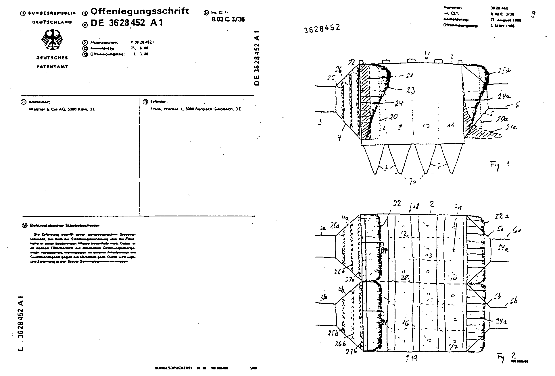
Fig. 2
Already at the early 1970s Walther ascertained that central vertical distribution had clear advantages for overall efficiency, provided that there was a flow maximum over the whole length of the ESP in the upper region which decreased appreciably down towards the hoppers. This kind of flow, described in the patent application (Fig.2), distribution is set by means of appropriate fittings built into the raw gas and clean gas hoods. Efforts are also made to arrange the raw gas ducting and the baffling in the raw gas hood in such a way that concentration of the dust content - but not of flow - reaches as high a level as possible before entering the first ESP field.
At this point it might be noted that the so-called "skewed gas flow technology" advocated in various publications evinces certain parallels with the Walther technology referred to above. However, the essential difference to the Walther technology is the lower maximum flow at ESP inlet. Walther's findings were based particularly on electrostatic precipitators with a rather low aspect ratio of down to 0.8. It was ascertained that the upward flow component towards ESP outlet, which is inevitable in a skewed flow system, had adverse effects on overall efficiency. That became even more marked when this upward component was concentrated on the last ESP field.

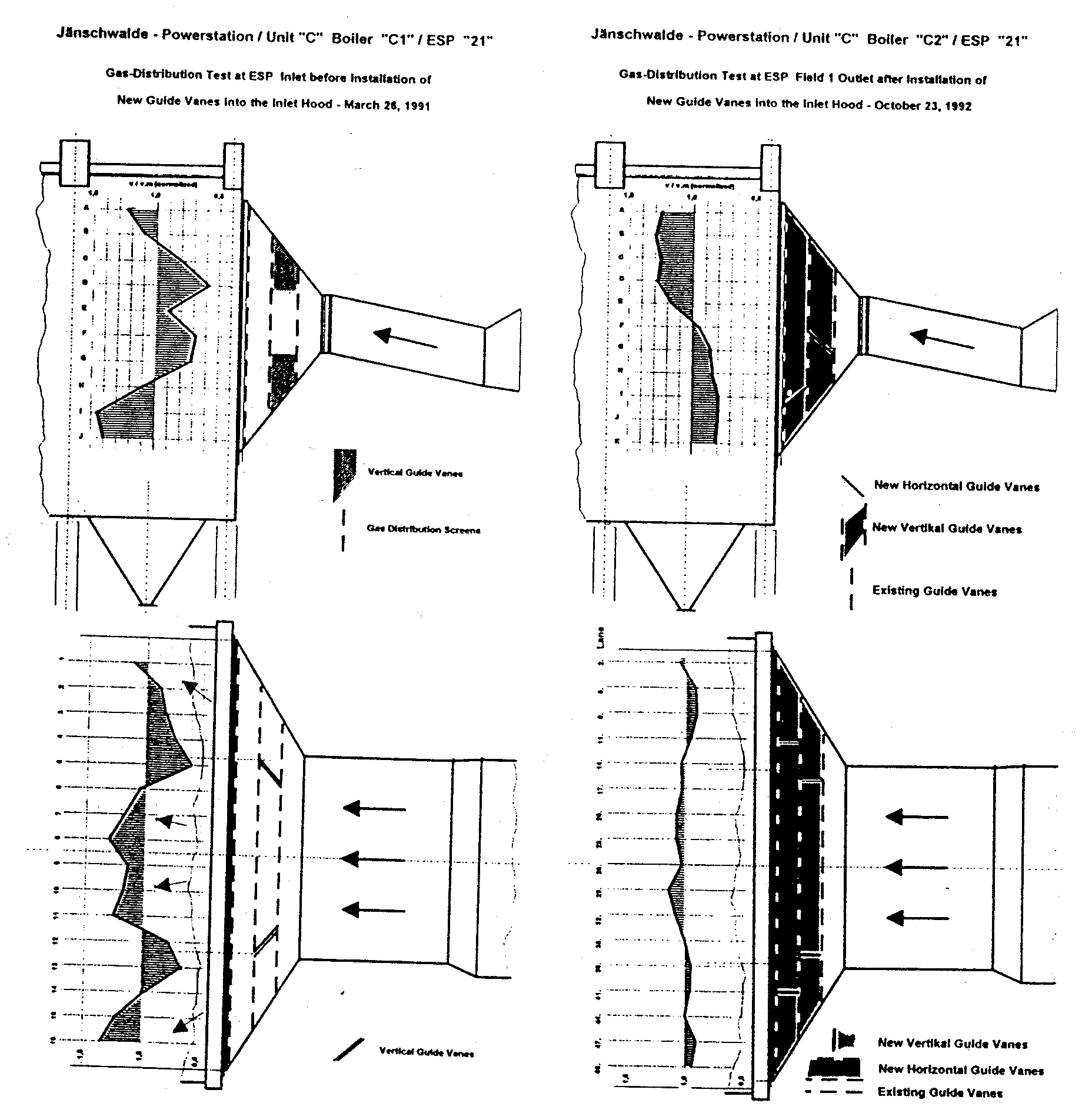
The contracting effect of most outlet flow systems makes it difficult to keep optimum flow distribution over length, height and width of the ESP without installing extra baffling in the clean gas hood. For this reason an "adjustable" gas distribution screen has been developed which not only enables flow into the ESP to be optimized. The baffle wall, consisting of adjustable U-profiles and flat plate sections, also acts as a moderate "Post-precipitator" for the charged dust exiting from the last field of the ESP. Between 1992 and 1995, 24 ESP's behind 12 lignite fired boiler units for a total of 3000 MW at Janschwalde power station have been refurbished by Walther. As acknowledged by the power station management, the tasks have been completed during very short outage periods and have led to remarkable results. Originally designed for an outlet dust content of 100 Mg/M3,Walther had to guarantee an emission limit of 50 Mg/M3 for the precipitators. The acceptance tests showed values in the range of 6,5 mg/m3 to 21,5 mg/m3, which have been achieved mainly through well engineered modifications on the flow distribution, installation of new rapping gear and some general repair work. As an example, figures 3 and 4 show the comparison of the flow distribution at ESP inlet before and after refurbishment.
Modifications of electrode geometry
Many improvements to ESP's can make use of the well-known advantages of increasing the spacing of the electrode passes. The enhancement factor on the kl value in the Deutsch formula may be expected in the order of considerable 1.05 to 1.10 when pass spacing is changed from, for instance, 300 to 400 mm ' depending on the nature of the application. An argument against increasing pass spacing may be the inhibiting effects of space charge. However, it must be added that in the majority of applications slight disadvantages due to space charge effects in the first field will be more than compensated in the following zones. In any case, increased pass spacing will necessitate new high voltage supplies with a directly proportional increase of peak voltage and an inversely proportional reduction of arithmetical current. It is obviously vital that the increased field strength in the ESP should not be limited by undersized support insulators or inadequate discharge gaps. This might even reverse the effect of increased pass spacing,
Modification of discharge and precipitation electrodes
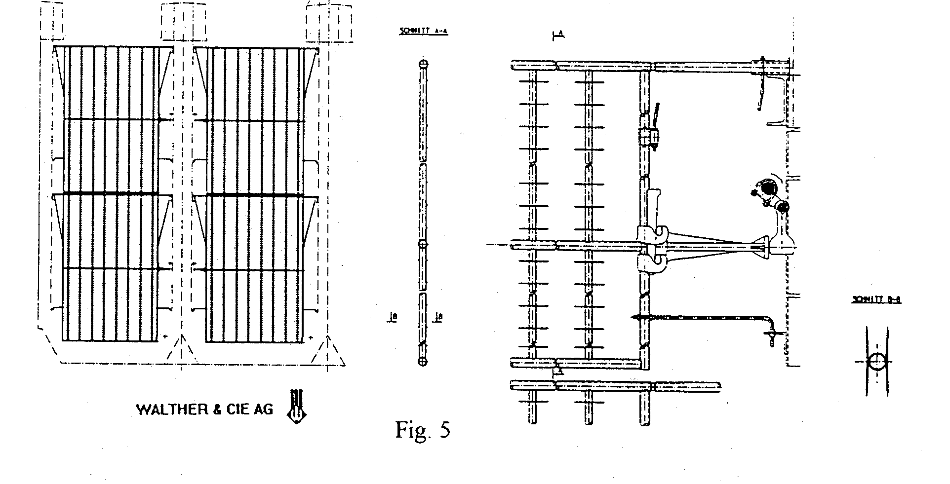
When a full renewal- of the inside of an ESP is scheduled the opportunity should be taken to install state of the art electrodes. For example, an innovative discharge electrode (DE) of conventional frame design with unbreakable rigid elements and a highly efficient rapping mechanism has been developed and installed with great success in a number of overhauled ESP's according to figure 5. The rigid DE elements are feasible with voltage/current characteristics according to the individual ESP requirements by varying the electrode prongs.

Modifications of high voltage supply systems
It goes without saying that the high voltage supply should be checked
over and, if necessary, replaced with state of the art equipment. This applies in general
to changes of pass spacing and sometimes also to changes of electrode geometry. On the
other hand, there are a number of applications which would not particularly benefit from
modernization of the high voltage equipment, depending on the previously observed
VI-behavior of the electrostatic fields. However, in case of severe back
ionization, the modernization of at least the control equipment will be necessary.
Using certain criteria modem controls are able to automatically set the individual zones
of the electrostatic precipitator to optimum performance. The question is always asked as
to how much the often considerable expense of installing new electrical equipment will
improve ESP efficiency. In the first instance experience generally shows that the
efficiency of the individual zones will increase with better power input in accordance
with the Deutsch formula. In difficult conditions - eg. back ionization - less power often
produces better results, particularly when outdated controls permit damaging current flow.
In applications of this kind the electrical equipment should certainly be modernized,
conceivably with micro-pulse high voltage supplies.
Improvements involving extensions of the ESP casing
When the casing of an ESP has to be extended in order to satisfy new
emission limits the usual scope of improvements is often exceeded and the task is more
like fitting a completely new system. Nevertheless, the recommendations made so far remain
applicable in full.
When dwelling time in the existing casing is too short one's first thought will be to
leave as much of the existing equipment as possible - depending on its state of repair -
where it is. This will often apply to foundations and supports, dust conveyors and ID fan.
What can then be done is to increase the electrode height, which, if pass spacing is
increased at the same time, can usually be achieved without putting any significant extra
burden on the foundations. Obviously, the adverse effect of a lower aspect ratio has to be
taken into account and optimum flow distribution becomes even more Important.
Adding active precipitation zones will normally be a less effective and a more expensive
way to increased SCA than increased electrode height with accordingly reduced average face
velocity. Widening the ESP system, ie. by adding precipitation surface in parallel, would
without any doubt produce the best results but this will generally be an uneconomic
proposition.
At this point brief mention might be made of an option that is becoming increasingly
popular, namely replacing the ESP fittings with pulse jet bag filters (PJBF). Examples
show that installing PJBF in an existing ESP casing can result in extremely high
collection efficiency at comparable cost. The feasibility of doing this is, of course,
always a question of individual onsite conditions. Installing ESP's as a first stage and
PJBF's in series can also be very beneficial. The downstream bag filter - which may be
fitted in the same casing - then only has to cope with a greatly reduced intake of charged
dust. Pilot systems in the USA have shown that this can result in appreciably higher
filtering speed with very moderate overall pressure loss.
Summary
The upgrading of ESP's is nowadays an exacting task, as it
requires most time the ESP efficiency to be increased with no extension of the available ground
space. Work of this kind must be based on thorough knowledge of the plant's operating
conditions, which should be optimized if possible. Some major general preconditions for
FGC applications were given. Examples show that exploitation of the full potential of the
existing volume of the ESP casing can often produce surprising results. Also increased
electrode height represents an economical solution.
Back to the This Old Box page.
Back to APC Network Main Page
Last updated: April 12, 1999.
Copyright © 1997 TRK Engineering Services, Inc. All rights reserved.
For more information contact: TRK Engineering Services - 95 Clarks Farm Road - Carlisle,
MA 01741 - Telephone: 978-287-0550 - Fax: 978-287-0569 - email: trkeng@apcnetwork.com