DIAGNOSTICS AND CONTROL OF ELECTRODE RAPPING SYSTEM
M. Koralun, A. Soltys, A. Babs
Instytut Energetyki, Gdansk, Poland
Abstract
The paper presents reliability aspects of the rapping system and gives some examples of defects observed in practice.
Various possibilities of the whole system inspection are discussed: from rapping power units up to individual hammers.
In the paper it described i. e.:
Introduction
A perfect electrode rapping is a prerequisite for good operation of the de-dusting facility. Destruction of even one of the hammers causes a significant fall of sparking voltage and drastic and long reduction of the dust collection efficiency of ESP.
In practice there was observed the following failures of rapping system:
In an extremal case, the standstill of the rapping of at least frame of electrodes causes:
Diagnostic possibilities
At the normal operation of the ESP, in which a rapping mechanism is entirely built into the chamber, hammers are not visible from outside. There are, however, different mediate methods of the rapping system operation.
1. Measuring of the current consumption by rapping power units does not require access to the mechanical arrangement. It allows it to detect only the following states:
- power shut-down;
- motor overload at full-phase operation;
- not-full phase state;
- motor overload at the non-full phase operation.
2. Inspection of the shaft rotation allows us - in addition - to detect the damage of the coupling (or the rotating insulator, in the case of the wire electrode rapping). This kind of inspection may be put into effect, e. g. by the toothed ring and a magnetic sensor.
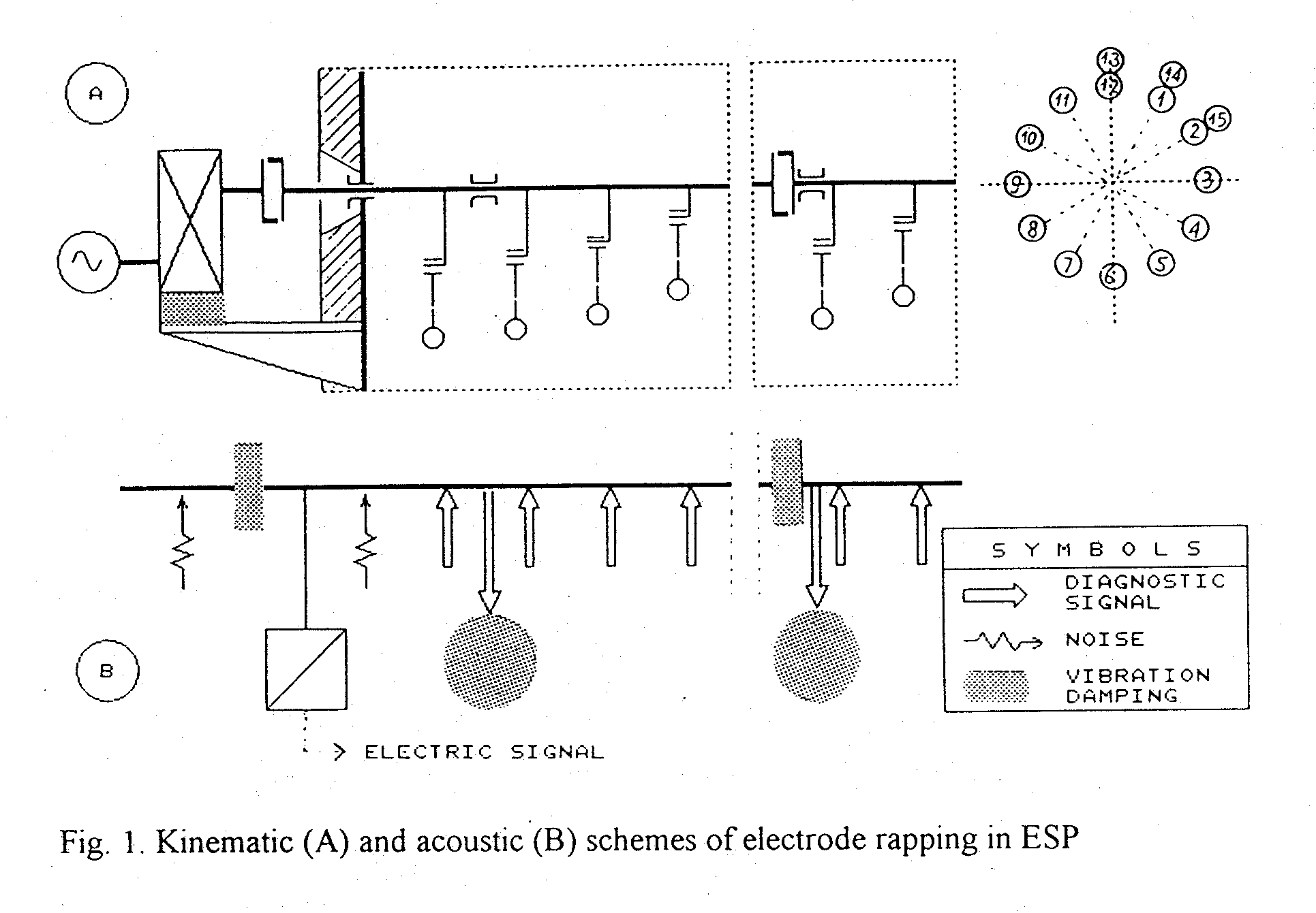
3. Measuring of the driving shaft vibration makes it possible to inspect the action of particular hammers. Fig.1 shows kinematic and vibroacoustic schemes of collecting electrode rapping system, containing, in this case, 15 hammers.
(On the vibroacoustic scheme, all reflecting elements are omitted.) The diagnostic signal, while passing along the shaft, is dumped by claw couplings and shaft bearings. It is also affected by noises coming from motoreductor and from other mechanisms placed on the same wall of the ESP chamber.
To assure a good receiving of the diagnostic signals from the shaft, some demands for
the mechanical part of ESP must be fulfilled; namely:
- significant reduction of the acoustic impedance of the inner coupling at the drive shaft;
- improved vibration dumping at the outer coupling;
- vibro-insulation of the motoreducer from its support construction.
It will be optimally to have an access to the free (i. e. opposite to the drive unit) end of the shaft, to built-in there an additive vibration sensor.
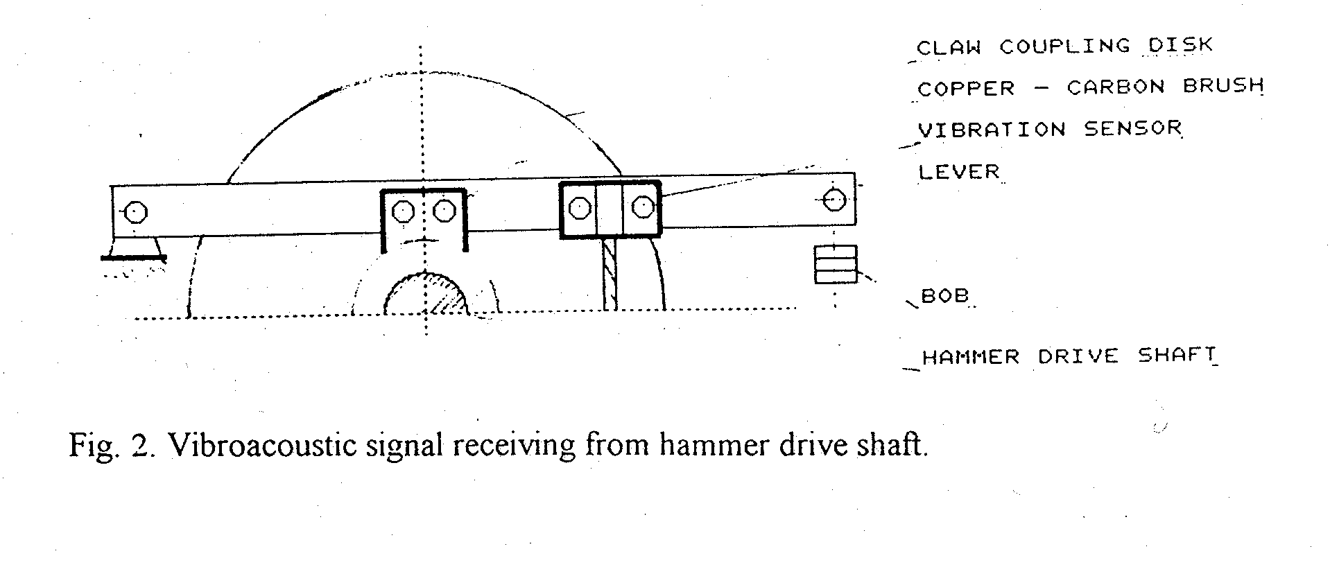
Fig. 2 shows an example of the arrangement for receiving vibroacoustic signal from the rapping mechanism.

The sensor is mounted on the lever suspended above the shaft and keeping in touch with them by the copper - carbon brush. The lever is additionally loaded with a bob to assure an optimum holding down the brush onto the shaft.
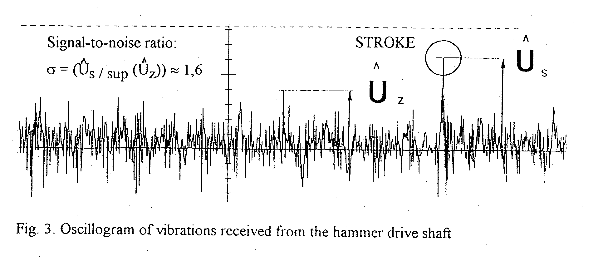
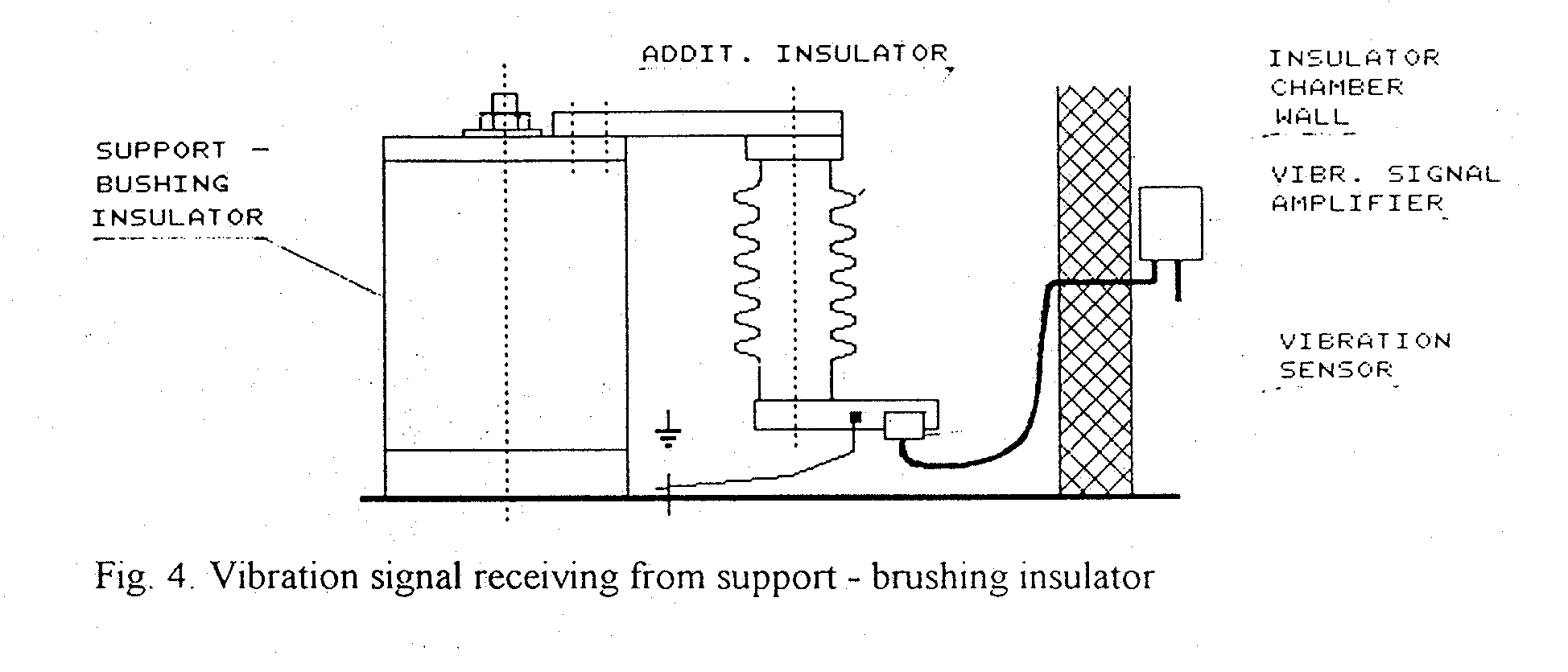
In the case, when the wire electrode rapping mechanism contains a rotating insulator (with two Cardan universal joints), the total sound dumping on the path from hammers to the end of the shaft is to great for the signal to be properly received by the sensor. (See Fig.3). In this case it is necessary to find another place to built-in the sensor. One of such places is the support - brushing insulator (see Fig. 4.).
Vibration sensor is here mounted on the additional insulator, joined rigidly with the main insulator cap. The signal-to-noise ratio, measured in this case was very advantageous, attaining up to
20%. Because of high temperature, the signal amplifier is remoted out from the insulator chamber
The system of the rapping diagnostic, elaborated by Institute of Power, Gdansk was installed in DOLNA ODRA Power Plant. For the wire electrode inspection, special, thermally resistant sensors were constructed. Their admitted working temperature is up to 130 0C.
Choice of vibration sensor
At the choice of the kind of vibration sensor the following factors must be considered:
1. Aim of the measure:
a) to determinate the electrode acceleration value at rapping.
b) to analyze vibrations propagation in the construction.
c) detection of impacts, examined as events on the background of noises.
2. Kind of the measure: temporary or
continuous.
3. Access and
thermal conditions at the place in which the sensor will be installed
4. Reliability and cost of all installation, containing, e.g. 20 or 30 sensors.
For initial measurements (1.a; 1.b) it is necessary to use a calibrated sensor, with a well-known frequency characteristic. In field investigations held so far, the authors used magnetoelectric piezoelectric and resistive sensors with the transfer frequency band of (3OHz-3 kHz).
For continuous operation in hardly accessible places, the especially designed, small
resistive sensors turned out to be the best at detecting strokes.
The family of sensors elaborated includes:
· The sensor without amplifier for measuring in extremely hard conditions (t <130
oC).· The sensor with a buffer amplifier, giving the linear current signal (20 mA), for registration of vibrations.
· The sensor with normalizing amplifier, giving (at the adjustable sensitivity) the binary output signal, destined for the rapping inspection.
The common advantage of all the sensors listed above is the relatively high level of the output signal, but with the necessity of an auxiliary powering (12 VDC). Their sensitivity is comparable to that of piezoelectric sensors.
Diagnostic and control system
The system may be of the passive or active kind of operation. In the first case its function is limited to signaling the imperfection of the rapping only. In the second case the system also involves the steering of individual rapping drives.
A microprocessor controller, called MSE, elaborated in the Institute of Power, Gdansk, is adjusted to control up to 24 drives. It replaces electromechanical relays, applied earlier. The block diagram of the control system is shown on Fig. 5.
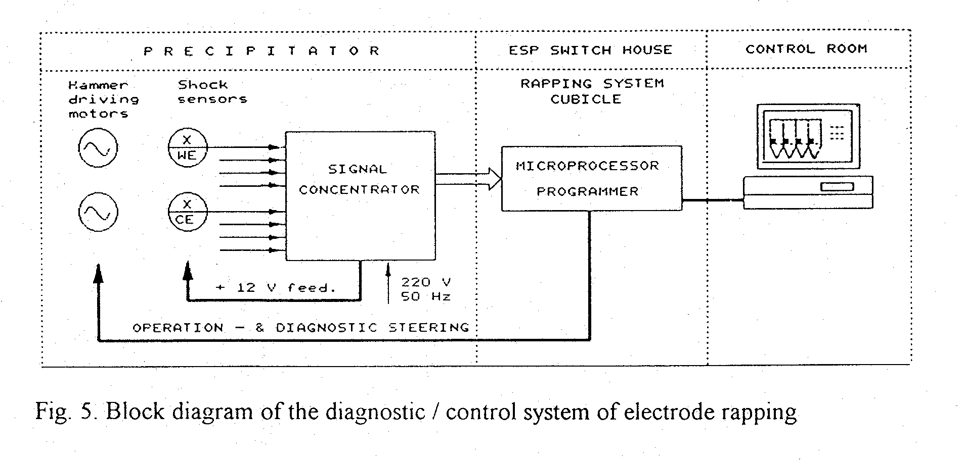
The controller changes periodically its function: from diagnostics to the operation steering. While "Diagnostics" (e. g. once a day), only one driver is put into operation, for one turn only. In this state all pulses received from sensors are counted and their number is compared with the number of hammers being mounted on the drive shaft.
When this equality is not fulfilled, an adequate signal is emitted by the controller and visualized on the screen of the process monitoring system.
While "Operation Steering", the controller actuates and brings to a standstill individual drives, according to the "time - table" written into its memory.
The pulses occurring at hammer strokes may be also used to the steering of the high voltage supply units. In this case ESP energizing is transiently interrupted (e. g. for the time of about 1 s), so, that the dust layer is falling out from electrodes in no-tension state. It makes the rapping more effective.
To reduce the overall length of cables to be installed, a signal concentrator was applied. The concentrator, containing auxiliary power supply (12 VDC) as well, was installed on a maintenance platform of ESP.
The system described above was put into operation in the KUJAWY Cement Plant, in. 1995. At present (June '96) a similar system is being installed in BELCHATOW Power Plant, Poland.
References
Koralun M. Diagnostics and control of electrode rapping system in ESP.
Part I. Mechanical problems. Biull. Inst. of Power, Warsaw.
Energetics No 9 /1994., p.339-334. (polish).
Part II. Sensors and control systems. Biull. Inst. of Power, Warsaw.
Energetics No 2 / 1996., p.94 97. (polish).