Electrostatic Precipitator
Specialists
Events Calendar
News Releases
This Old Box Newsletter
Swap Shop - Used Stuff
Sales Items - New Stuff
Books & References
Employment Opportunities
Professional Organizations
ESP Terminology
ESP Photographs
Consultant
Organizations
OEMs
Rebuild, Parts & Construction
Accessory Products & Equip.
Lab/Testing/Modeling Co.
Contact us at
trkeng@apcnetwork.com
Managed by:
TRK Engineering Services
Information on:
TRK Engineering
Precipitator
Seminars
Remote
Monitoring
|
| Pictures
Insulators in the ESP |
Back to |
Insulators are used in numerous locations in the
precipitator high voltage system. Common
types of insulators and usage include support insulators which support and
isolate the discharge electrode system, standoff, post and through bushing
insulators to support and isolate the high voltage bus, insulated rapper
rods to transmit rapping energy to and isolate the high voltage discharge
electrode frames, and anti-sway insulators to prevent movement of the
discharge electrode frames. Failure
of an insulator can cause grounding and other ESP operational problems.
Failure is usually of an electrical, mechanical or thermal nature.
|
|
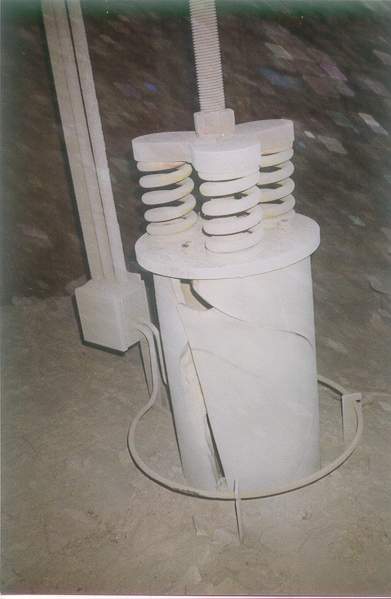
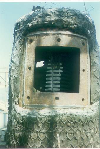
The high voltage support insulator is badly damaged.
Failure is likely attributable to a combination of thermal
stress and electrical arc-over due to contamination of the insulator
surfaces. This
precipitator has no purge blower system and the ring heaters were
inoperative. |
|
|
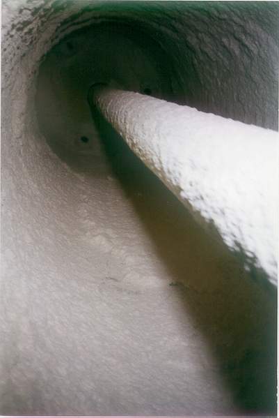
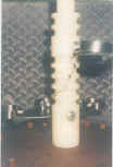
It is important to maintain cleanliness of the inside
and outside surfaces of HV support insulator.
The inside surface of this insulator is contaminated due to
ineffective introduction of purge air.
The elbows at the top of the photo are installed incorrectly.
They are designed to be oriented either all clockwise or all
counter-clockwise to swirl air flow tangentially around the inside
surface of the insulator to maintain cleanliness.
Here the elbows are not oriented correctly. |
|

|
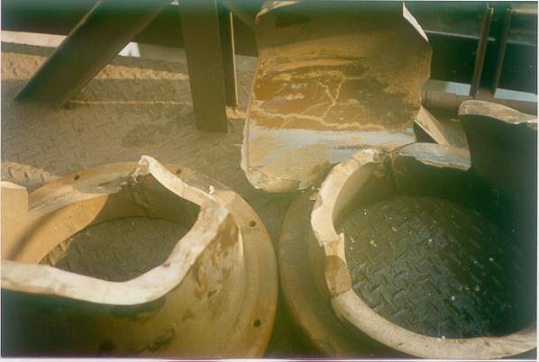
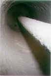
Note the burn marks from electrical
tracking on these sections of failed support insulators.
These will produce a high resistance or dead short condition
in the associated bus section and will detract from ESP operation. |
|
|
|

|
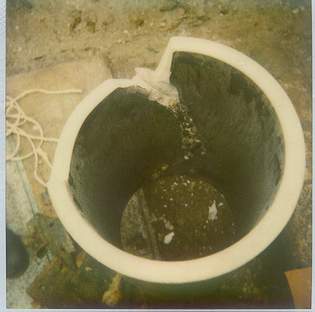
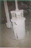
The standoff
insulator in this bus duct has failed due to a hole in the duct
overhead which allowed water to penetrate.
|
|

|
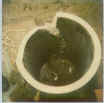
This HV rapper rod insulator is damaged due to high
intensity rapping and loose coupling bolts.
Another frequent cause of failure is water penetration due to
damaged rapper boot seals. |
|
|
Electrical
tracking on the internal selector switch post insulator for a
transformer rectifier. Cause
of failure is the result of changing switch positions while the
transformer was energized.
|
|
|
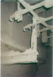
Anti-sway insulators are installed in some ESPs to
prevent on-line movement (swinging) of the lower discharge electrode
frames. It is important
that they be oriented so as to avoid material buildup and installed
to maximize tracking distances.
They are designed to maintain the collecting plate to
discharge electrode alignment, not to obtain it.
The anti-sway insulator in this photo needs to be lowered to
optimize tracking distances. |
Back to APC
Network Main Page
|