Electrostatic Precipitator
Specialists
Events Calendar
News Releases
This Old Box Newsletter
Swap Shop - Used Stuff
Sales Items - New Stuff
Books & References
Employment Opportunities
Professional Organizations
ESP Terminology
ESP Photographs
Consultant
Organizations
OEMs
Rebuild, Parts & Construction
Accessory Products & Equip.
Lab/Testing/Modeling Co.
Contact us at
trkeng@apcnetwork.com
Managed by:
TRK Engineering Services
Information on:
TRK Engineering
Precipitator
Seminars
Remote
Monitoring
|
| Pictures
of Air Inleakage in the ESP |
Back to |
Air / water inleakage can have a drastic adverse affect on
precipitator operation. When
outside air / water is drawn into the precipitator system, gas volume, gas
velocities, gas temperature and moisture content of the gas is affected
which can modify resistivity and reduce treatment time.
Additionally, inleakage promotes corrosion and can cause
reentrainment of collected material. Sources
of air inleakage are often ignored as insignificant, however, their
cumulative affect can be great. Below
are examples of typical Sources of inleakage.
|
|
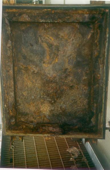
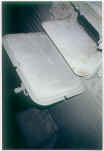
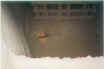
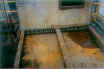
The
ash patterns on the inside of this hopper door indicate air
inleakage. Air inleakage
in the hopper area can cause reentrainment of collected material as
well as corrosion of overhead collecting plates. |
|
|
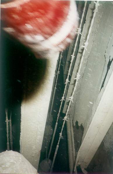
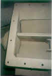
Holes
in a side access door coaming allow outside air to penetrate the
ESP, causing zones of high velocity and corrosion of internal
components. |
|

|
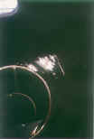
The
collecting plate shown in this photo is adjacent to a leaking side
access door. Air
inleakage has destroyed the lower portion of the collecting plate.
The resulting jagged edges will promote spark-over and lead
to the eventual failure of adjacent electrodes. |
|

|
Corrosion of inner
surface of access door due to air inleakage. |
|
|
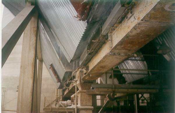
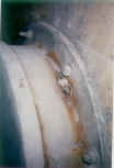
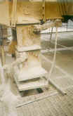
Eliminating
air inleakage in the hopper area is crucial to reducing corrosion,
and to preventing reentrainment of collected material and hopper
plugging. TOP:
Note evidence of air inleakage at the hopper flange.
BELOW: Material
handling systems (screw conveyor) are often sources of air
inleakage. |
|

|
|
|
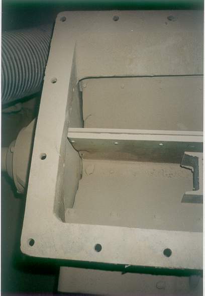
Although
rotary valve blades allow adjustment to obtain a seal, this valve is
worn along the edge and allowing air inleakage.
|
|
|
Both double dump valves
are propped open. This
may temporarily help material flow, but the resulting air
infiltration can cause hopper buildups, corrosion and dust
reentrainment. |
|

|
The open test post in the
inlet duct is a source of inleakage. |
|

|
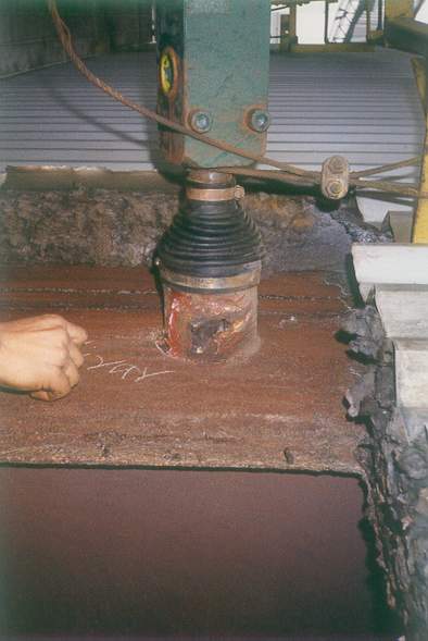
Inspect
rapper boot seals and pipe sleeves as sources of inleakage. |
|
|
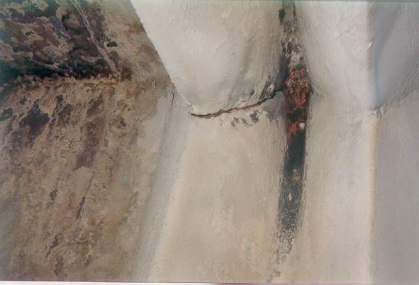
The insulation was
removed from the precipitator inlet ductwork to expose large
corrosion holes over the entire length of duct.
These holes allowed for significant inleakage.
ESP performance would vary with temperature and
weather conditions. |
|
|
Slide gates can be a
source of inleakage. Seals
should be inspected and replaced if evidence indicates inleakage |
|

|
Inspect
integrity of expansion joints and repair or replace as necessary to
eliminate inleakage. |
Back to APC
Network Main Page
|