Electrostatic Precipitator
Specialists
Events Calendar
News Releases
This Old Box Newsletter
Swap Shop - Used Stuff
Sales Items - New Stuff
Books & References
Employment Opportunities
Professional Organizations
ESP Terminology
ESP Photographs
Consultant
Organizations
OEMs
Rebuild, Parts & Construction
Accessory Products & Equip.
Lab/Testing/Modeling Co.
Contact us at
trkeng@apcnetwork.com
Managed by:
TRK Engineering Services
Information on:
TRK Engineering
Precipitator
Seminars
Remote
Monitoring
|
| Pictures
of Alignment Issues in the ESP |
Back to |
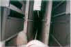
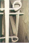
Good collecting plate to discharge electrode alignment is
important to optimum ESP operation. Close
clearances and jagged or sharp edges will promote premature spark-over which
can limit power and ultimately, the efficiency of the precipitator.
|
|
The electrode should be centered in the gas
passage between the adjacent collecting plates.
Allowable tolerances vary with a number of factors however,
most manufacturers specify 1/4" of center for initial
installation of wire electrodes in a new ESP.
Equally important is the position of the electrode relative
to the stiffener baffles on the collecting plates.
Electrodes should be centered between stiffener baffles.
The stiffener baffles provide a "sharp" edge which
can promote sparking when in close proximity to a discharge
electrode. Minimum
acceptable clearances are usually 1-1 ½ times the acceptable cross
gas flow tolerance. Shrouded
wire discharge electrodes help to prevent spark-over to the top and
bottom collecting plate stiffeners.
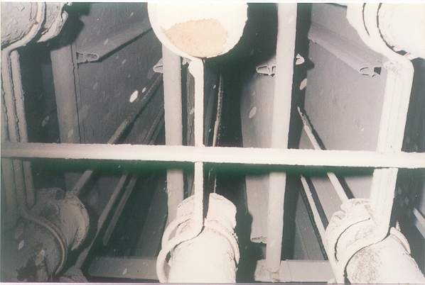
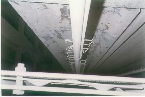
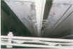
In the TOP photo the discharge electrodes are not
centered properly in the gas passage and need to be centered.
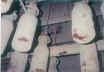
The barbed wire electrodes in the photo BELOW are in
too close proximity to the collecting plate stiffener baffles and
need to be repositioned.
|
|
|
|
|
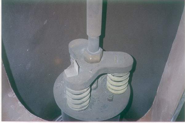
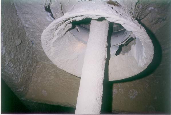
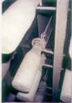
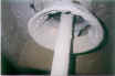
When
a high voltage support insulator is replaced, the collecting plate
to discharge electrode alignment can be affected and should be
checked. Once proper
alignment has been established, the retainer angle on the support
nut should be reinstalled to prevent movement of the support nut.
The nut maintains the relative position of the collecting
plates and discharge electrodes |
|
|
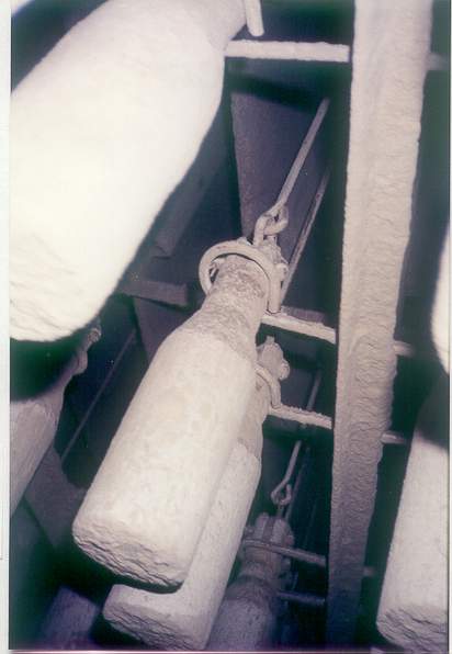
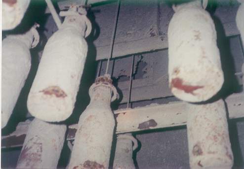
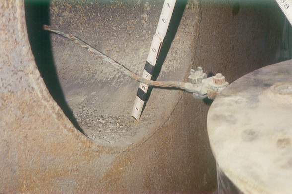
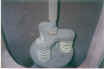
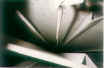
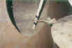
Inspect
the position of the wire discharge electrode weights in the lower
weight guide frame. There
should be no binding of the weight in the guide frame and there
should be adequate allowance for thermal growth.
Note the position of the weights in the TOP photo.
The position of the lower weight guide frame does not allow
for any on-line thermal expansion of the wire electrode without the
weight bottoming out in the guide frame.
This reduces tension on the associated wire electrode and
allows it to go slack and whip in the gas stream.
The movement of the electrode in the gas stream causes
repeated localized spark-over which will adversely affect power
levels and will lead to the eventual failure of the wire.
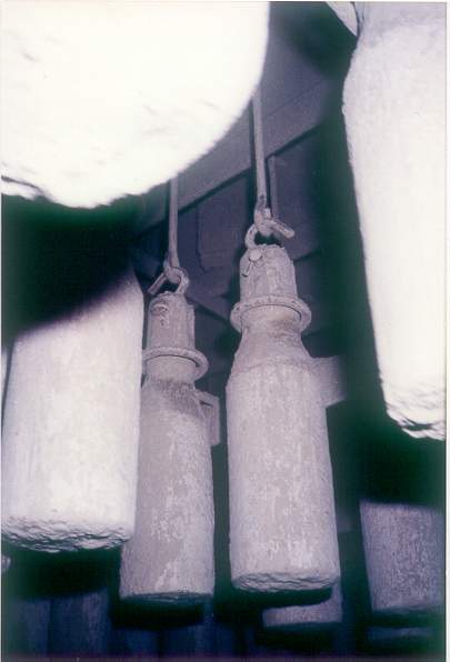
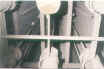
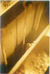
The weights in the photo below BOTTOM are positioned properly.
Tensioning of hanger wires / cables should also be verified. |
|
|
|
|
Collecting plates that have been damaged
due to corrosion, bowing or repeated erosion from spark-over can
provide a jagged edge or reduced clearance that promotes premature
spark-over. Discharge
electrode wires adjacent to damaged sections of collecting plate
should be removed, or the collecting plate should be repaired. |
|
|
|
|
Kinks in the discharge
wire create a close clearance to the plate baffles. |
|
|
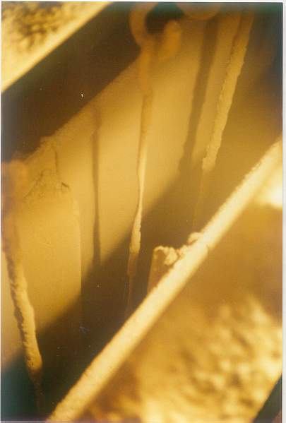
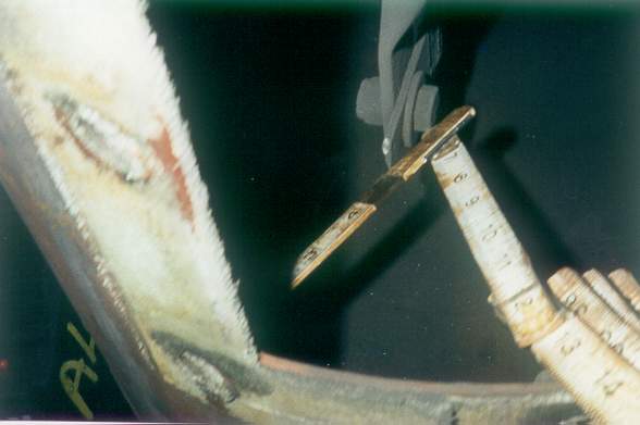
Note the erosion
of the discharge electrode wire shroud and collecting plate
stiffener baffle due to spark-over from reduced clearance.
|
|
|
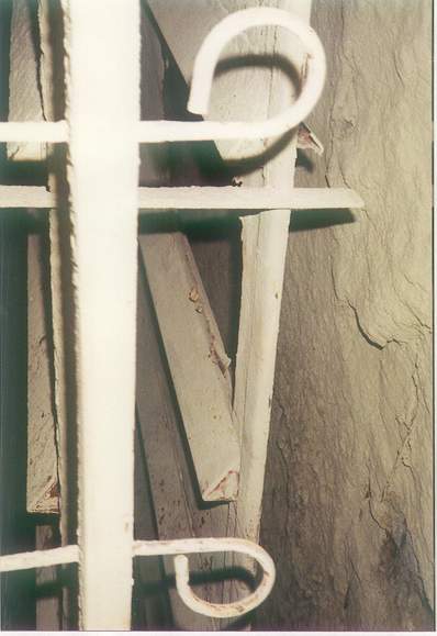
Corrosion of the corona
shield on the underside of the support insulator provides a jagged
edge which promotes spark-over. |
|
|
Bent
emitting pins / spikes on rigid discharge electrodes (RDE) |
|
|
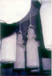
The high voltage
connection is not centered in the bus duct and does not provide
sufficient clearance.
|
|

|
This
bus bar is not centered properly in the duct and is promoting
spark-over. The white
discoloration on the tip of the bar is evidence of corona
generation. |
Back to APC
Network Main Page
|