Electrostatic Precipitator
Specialists
Events Calendar
News Releases
This Old Box Newsletter
Swap Shop - Used Stuff
Sales Items - New Stuff
Books & References
Employment Opportunities
Professional Organizations
ESP Terminology
ESP Photographs
Consultant
Organizations
OEMs
Rebuild, Parts & Construction
Accessory Products & Equip.
Lab/Testing/Modeling Co.
Contact us at
trkeng@apcnetwork.com
Managed by:
TRK Engineering Services
Information on:
TRK Engineering
Precipitator
Seminars
Remote
Monitoring
|
| Pictures
of Gas Distribution Problems in the ESP |
Back to |
Good, uniform gas distribution is important to ESP
performance. Poor gas
distribution can diminish ESP performance by creating high velocity zones
which reduce treatment time of the gases, allowing gases to bypass the
treatment zone of the ESP, reentraining collected material back into the gas
stream, and promoting material buildup.
Gas distribution can often be evaluated in the field during a dirty
inspection of the ESP by observing buildup patterns, or the lack of them, on
the internal components of the ESP and inlet and outlet ductwork. Corrective
measures can often be implemented without the need for a model study.
Air infiltration is an external factor that can significantly impact
gas distribution.
|
|
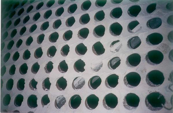
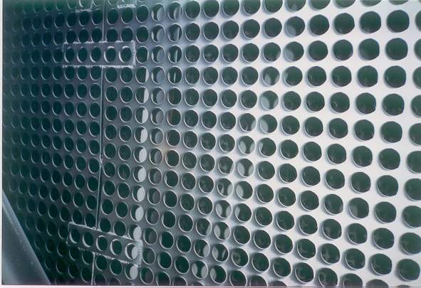
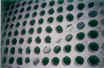
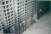
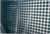
Gas distribution can be evaluated by observing buildup
patterns. The buildup on
the downstream side of this perforated plate indicates gas flow is
expanding downward and to the left.
These patterns can be used to devise corrective measures. |
|
|
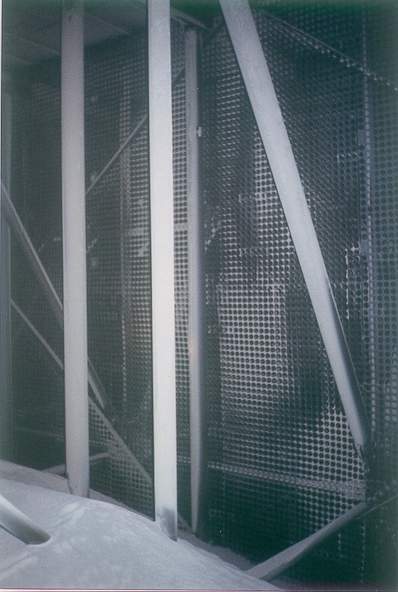
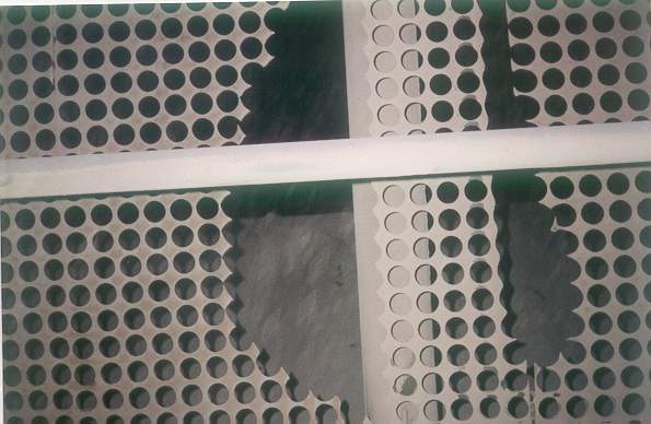
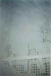
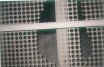
Perforated gas distribution plates help to promote
uniform gas distribution. If
buildup occurs, for whatever reason, it can cause distribution
problems in the ESP, which can lead to performance problems. |
|
|
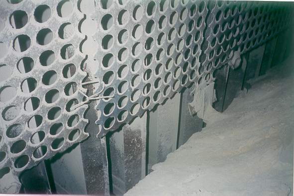
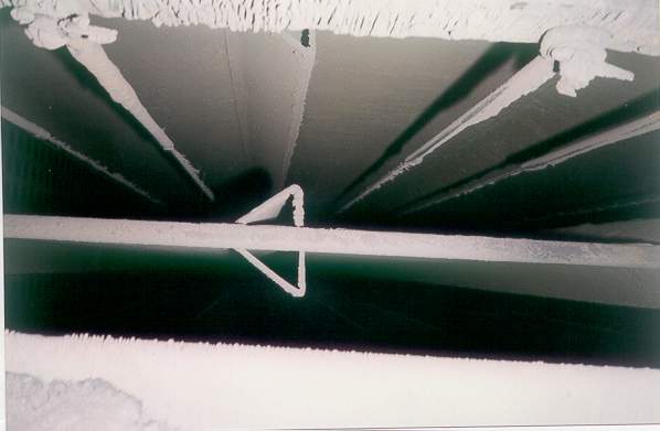
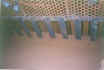
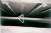
The perforated plate at the inlet flange
to the precipitator has been cut along the bottom to promote
material flow into the hopper. This
has produced a high velocity zone at the bottom of the treatment
zone evidenced by scouring of the lower portion of the collecting
plates. It also is
promoting reentrainment of collected material in the hopper back
into the gas stream. BELOW:
The installation of a "snowfence" at the bottom of the
perforated plate maintains gas distribution while at the same time
allowing material to flow into the hoppers. |
|
|
|
|
Blockage of the inlet turning vanes will create gas
distribution problems in the ESP. |
|
|
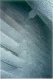
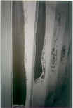
The collecting plates, wire electrodes and weights are
scoured clean, indicating a very high gas flow and sneakage along
the bottom of the ESP. |
|
|
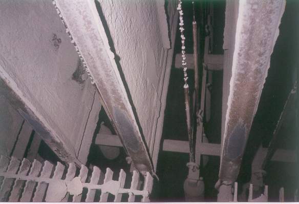
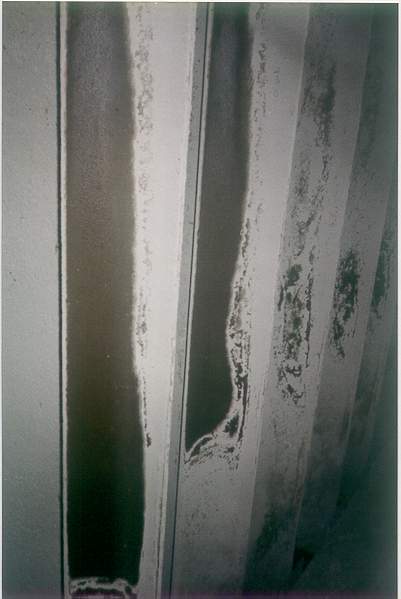
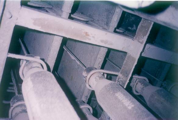
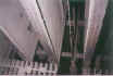
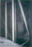
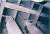
A
void created by improperly installed turning vanes, located upstream
of the pipe supports and perforated plates, can be seem by the heavy
material deposits on the vertical support pipes.
This type of buildup indicates little or no flow.
One would expect the pipe to be bare metal clean from this
angle. A close look at
the perforated plate also shows a reverse flow pattern back through
the plate. Because the
gas is trying to fill this void. |
|
|
|
|
Channeling of gases down the middle of an inlet nozzle
has caused erosion of the perforated gas distribution plate.
This will produce a high velocity zone in the precipitator. |
|
|
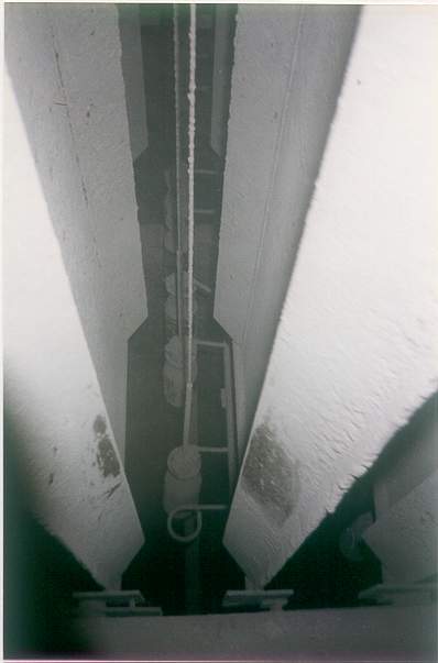
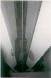
The polished sections of the wire electrode shrouds
indicate gas flow above the treatment zone. |
|
|
Polishing
of the collecting plates in the first field indicates high gas flow
along the bottom of the precipitator.
This can cause reentrainment of the dust and allow gas to
bypass the treatment zone by sneaking under the field.
It can also cause the wire electrodes to swing, reducing the
spark-over voltage and fatiguing the wires. |
|
|
Buildup patterns on the wire shrouds and weights
indicate significant gas flow beneath the collecting plates. |
|
|
This pattern was evident all the way through the ESP.
The collecting plates were polished in the fourth (outlet)
field. |
Back to APC
Network Main Page
|